Shipping Will Resume Jan 5th 2026

How to Assemble Your Super Deluxe 8/16bit Joystick Kit

Step 1

  • 1.1 Insert 4 of the M3 x 16mm annodised hex screws through the rubber feet and on through the bottom panel of the casing.
  • 1.2 Fasten down the 40mm standoffs onto the inserted screws.
  • 1.3 Insert the 4 M2.5 x 16mm nylon screws into the bottom panel.
  • 1.4 Place the 3D printed PCB spacer over the nylon screws.
  • 1.5 Place the PCB onto the spacer and screws.
  • 1.6 Fasten down the PCB onto the nylon screws using the 4 2.5mm nylon hex nuts.

Step 2

  • 2.1 Insert the rocker switch into the rear casing panel.
  • 2.2 Bring the 4 side panels together and lower them into the corresponding slots on the bottom panel, you will have to tilt the rear panel back to get it past the DE9 Connector on the PCB.

Step 3

Using the 4 countersunk M5 screws and 4 M5 nuts fasten the joystick to the 5mm top panel, the nuts have a nylon thread lock so you will have to use an 8mm spanner or a pair of pliers to hold the nut in place while you tighten the screws.

Step 4

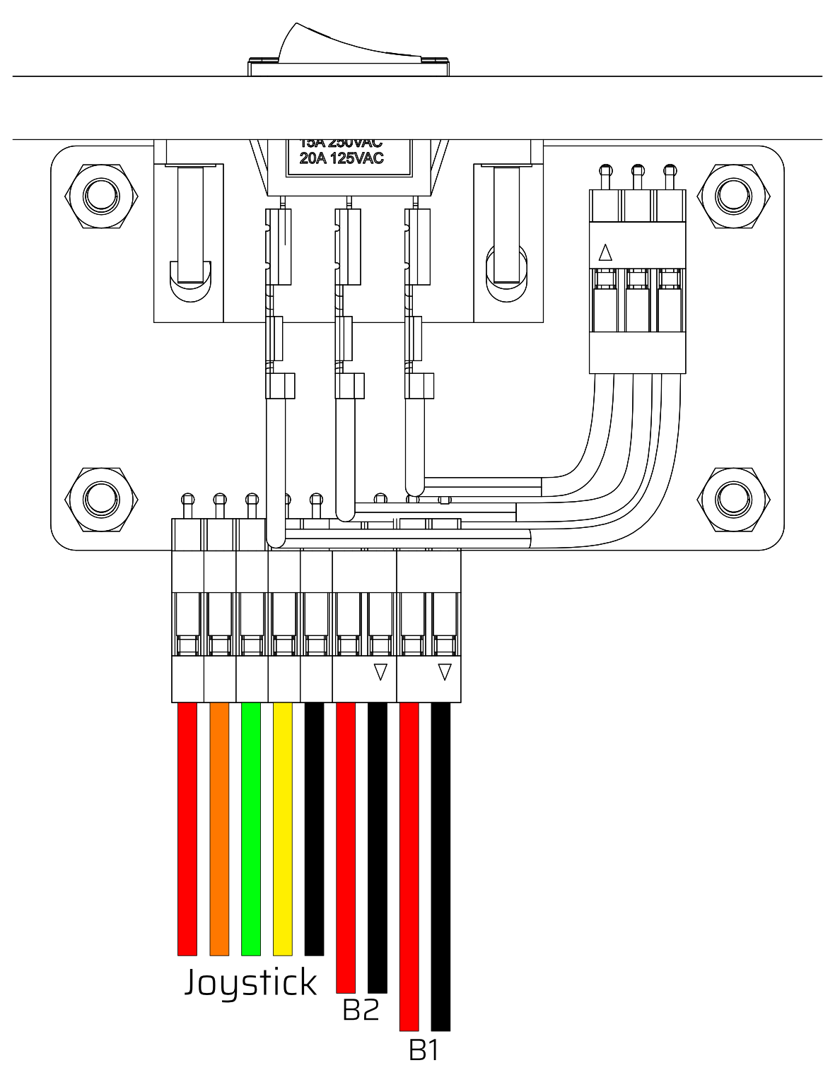
Attach the small cable with 3 spade terminals to the rocker switch with a red-black-red sequence and connect the 3 pin dupont connector on the other end to the PCB.

Step 5

Joystick On The Left

  • 5.1 Attach the 5-pin joystick cable to the first 5 pins on the PCB, you willl need to attach them in the following order from left to right
    • Red - Up
    • Orange - Down
    • Green - Left
    • Yellow - Right
    • Black - GND
  • 5.2 Attach the 2-pin button cables to the last 4 pins on the PCB, they will correspond to button 1 and button 2 as illustrated.

Joystick On The Right

  • 5.1 Attach the 5-pin joystick cable to the first 5 pins on the PCB, you willl need to attach them in the following order from left to right
    • Orange - Up
    • Red - Down
    • Yellow - Left
    • Green - Right
    • Black - GND
  • 5.2 Attach the 2-pin button cables to the last 4 pins on the PCB, they will correspond to button 1 and button 2 as illustrated.

Step 6

  • 6.1 Connect the spade terminal connectors to button 1 and button 2 through the corresponding holes in the 3mm top panel.
  • 6.2 Push the buttons into the holes in the 3mm top panel.
  • 6.3 Connect the 5-pin JST connector to the joystick, the connector is keyed with a clip so it can only be connected one way round.
  • 6.4 Align the 3mm and 5mm top panels and then place them down onto the rest of the casing assembly.
  • 6.5 Place the joystick dust cover over the joystick shaft.
  • 6.6 Screw down the ball top onto the joystick shaft.

Step 7

Attach the final 4 M3 x 16mm annodised hex crews into the corners of the 3mm top panel.

You have now fully assembled your joystick, if you have had any issues or have any feeback please feel free to reach out to us at info@monsterjoysticks.com