How To Assemble Your Super Deluxe CD32 Retro Joystick Kit
The assembly of the Monster Joystick is designed to be simple and only require a few tools, this assembly guide has been broken down into multiple steps with photos to help you along the way.
Before starting assembly it is advised that all protective films are removed from all of the laser cut pieces.
Step 1 - The Bottom Panel
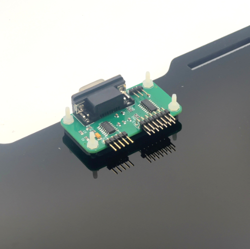 |
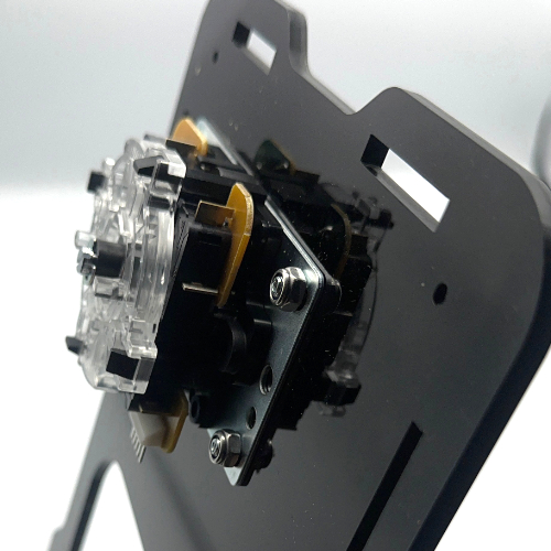
Using the 4 x 16mm M2.5 nylon screws, 4 x M2.5 nylon nuts and the 3D printed spacer, attach your CD32 interface to the bottom panel. Thread the nylon screws through the panel, place the spacer onto the screws and then the PCB onto the spacer and screws, use the nylon nuts to gently fasten them all together. This can be done by hand as components on the board could be easily damaged. |
|
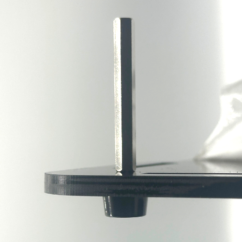
Attach the internal standoffs and bottom feet by threading 4 of the provided M3 anodised hex screws through the feet, then through the bottom panel and fasten the standoff to the screw. |
 |
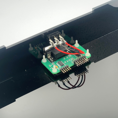 |
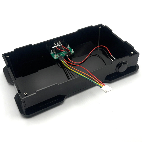
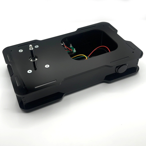
Attach the small cable with 3 spade terminals to the provided rocker swith with a red-black-red sequence, then thread the cable through the switch hole on the rear panel. gently push the switch into the socket and connect the 3 pin dupont connector end to the interface PCB. You can now align and insert the back panel into the bottom panel as pictured. You can now connect this button to the first pair of pin headers (leftmost) on the interface PCB. |
Step 2 - Side Panels
|
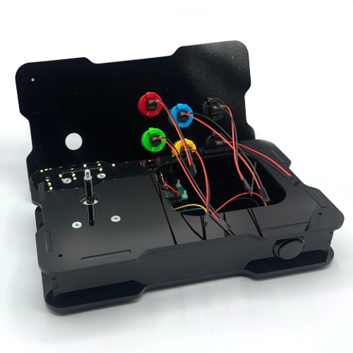
Align and slot in the left and right panels into the base panel of the joystick, please be sure that the side with the shorter dovetails is facing towards the front of the base. You can then insert a black pusk button into the front panel and connect 1 of the 2 wire terminal cables to the button. now align and insert the front panel into the base panel. Now you can attach the 5 pin joystick cable to the interface PCB, you willl need to attach them in the following order from left to right
|
 |
Step 3 - Joystick & Buttons
 |
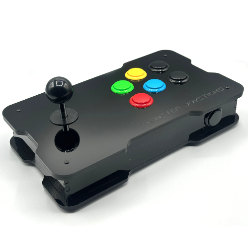
Using the countersunk M5 screws and nuts fasten the joystick to the 5mm top panel pictured, the nuts have a nylon thread lock so you will have to use an 8mm spanner or a pair of pliers to hold the nut in place while you tighten the screws. |
|
Now position the panel on top of your current case assembly. |
 |
 |
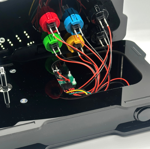
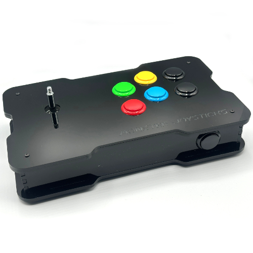
You can now add the remaining buttons to the 3mm top panel and then connect the remaining 2 wire cables to the terminal connections on the buttons. |
|
Connect the top panel buttons to the remaining pins on the interface PCB from left to right.
|
 |
Step 4 - Final Assembly
|
The top panel can now be placed on the top of the joystick, place one of the provided dust covers over the joystick shaft and scew the ball top onto the joystick. |
 |
 |
It's now time to fasten the final 4 M3 anodised hex screws into the internal standoffs through the top two panels as illustrated. Congratulations! You have now assembled your Deluxe CD32 Joystick. You can now proceed to connecting it to your CD32/Amiga system. |